Sunday, December 22, 2013

It's all about the paste


I finished building the last few BGA test boards today and learned a bit.  Here's an overview of my results including all six cards per component:

Part Type Total Qty Qty Failed Yield
0805 18 0 100%
0603 12 0 100%
0605 (LED) 48 2 95.8%
0402 24 0 100%
QFN (0.65mm pitch) 6 0 100%
BGA (0.5mm pitch) 6 1 83.3%

I was able to correct the LED soldering issues by hand; I think that the parts were a little misaligned when I placed them.  The BGA issue looks like a short.  I'll do some more testing to try to confirm that.

Fortunately I was able to improve my assembly process and the last three boards built were trouble-free.  The most important improvement that I made while building the last three cards was to secure the stencil on only one side so that I could remove it quickly and avoid smearing the paste:


This method allowed for a very clean application of paste:


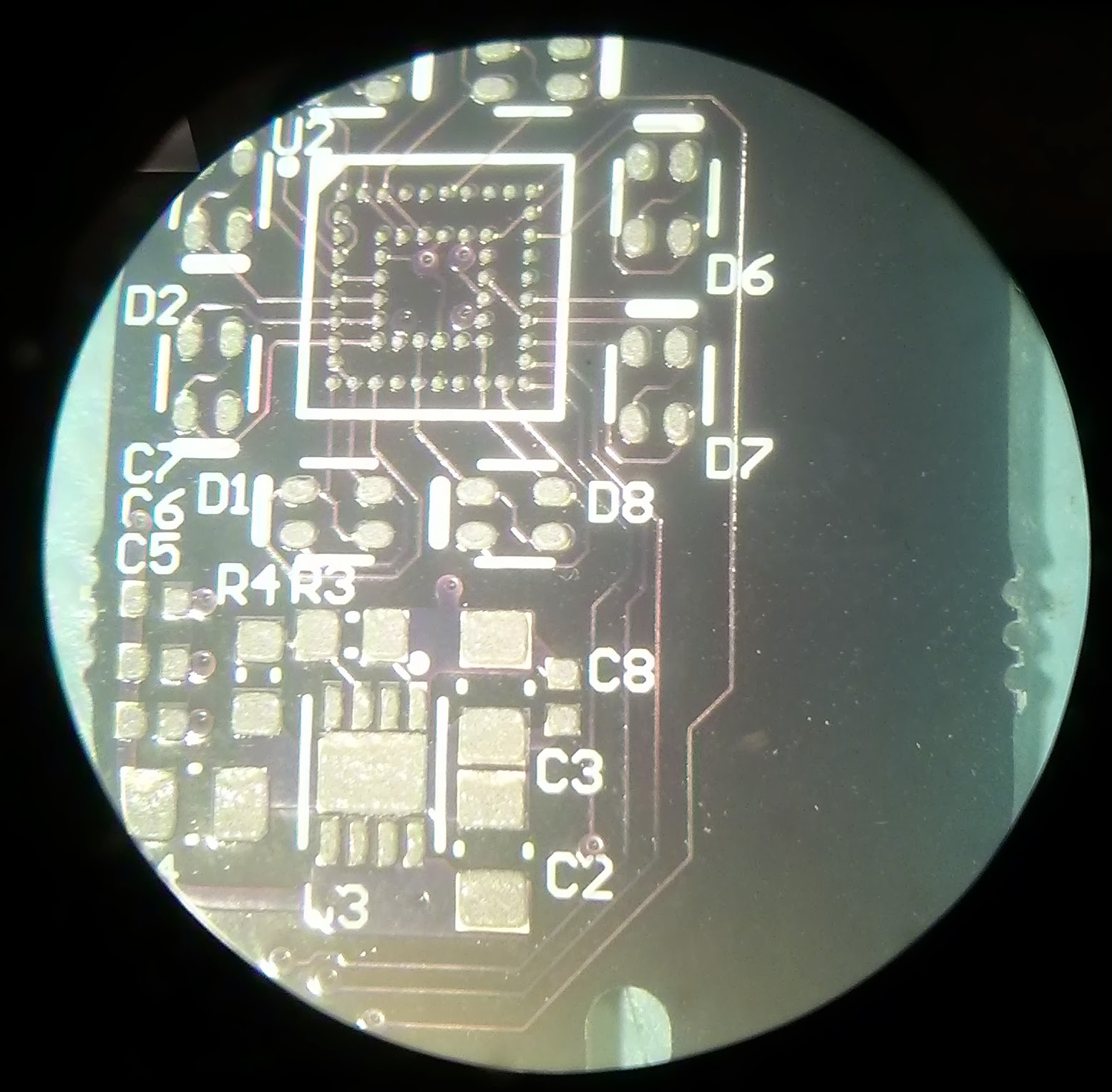
Better assembly led to prettier pictures:


Friday, December 20, 2013

Who afraid of 0.5mm?

Success! I was able to solder a 0.5mm pitch BGA on my bityBGA board tonight and only had to reflow a single joint by hand. I thought that a step-by-step guide would be interesting, but before I get into that a little background on bityBGA might be helpful. I designed the board to give me quick pass or fail feedback about whether the BGA CPLD was soldered correctly. I connected each CPLD I/O pin to a another non-adjacent I/O pin and then to the anode of a one color of a bi-color LED and the cathode of the other color:


This arrangement allows me to alternatively light either the red or green half of the bi-color LED.  To light the green LED I tri-state the red I/O pins, then drive the green anode high and the green cathode low.  Since adjacent pins are always either driven high or low I can identify BGA shorts.

While preparing to solder I ran quite a few temperature profiles.  I used Altera's SMT Board Assembly Process Recommendations (AN-353-4.0) to design my profile.  The target was to pre-heat at between 150 and 200 degrees Celsius for 60-120 seconds then heat between the eutectic and the CPLD's maximum temperature for another 60-120 seconds.  I profiled to PCB using some thermocouples, a Meterman meter with an RS232 interface, and a simple python script that I wrote to plot the temperature data against my profile in real time:


The green line in the plot above is the temperature on the PCB where the CPLD will be installed.  The yellow line is the temperature on the PCB at the component farthest away from the CPLD.  With a verified profile, the next step was to align the stencil:


Apply the paste:


Carefully remove the stencil:


Place the components:


Place some thermocouples to monitor the heating:

Heat the board:

Test it:


Next I'll build a few more to see how repeatable my process is.

Wednesday, December 18, 2013

Stencils

I ordered a low-cost mylar stencil form Pololu.  The total cost for a 2 square inch stencil was $31.95 (including shipping).  They charge $25 for the first 4 square inches and $1 per additional square inch.

After placing the Pololu order I found another stencil house with better pricing: OHARARP.   My total cost with OHARARP was $30.60 (including shipping) for six different stencils that fit on an 8.5" x 11" kapton sheet.  You can send up to six paste layers from different designs and OHARARP will automatically panelize them and separate the stencils before shipping.

For reference I've included a few pictures of the stencils below.  The OHARARP kapton stencils have much cleaner edges:

Pololu Stencil

OHARARP Stencil

Closer view of the stencils.  The OHARARP stencil is on the left.


Saturday, December 14, 2013

New toys

I received my bityBGA boards today.  I'll use these boards to practice installing parts using solder paste and my IR reflow station.  If all goes well I'll post a video of the reflow process.

Friday, December 6, 2013

Strange bedfellows

How do you get ready to solder an Altera BGA?... with a Xilinx BGA, of course

I intend to build the rev B bityExpress prototype entirely on my own this time including the 484 pin BGA (Altera FPGA).  Since the part is so expensive I decided to practice on a simpler card with a cheaper BGA.  The result was a small, 2 layer PCB:

Layer 1 check-plot of bityBGA

I was hoping to use an Altera Max V CPLD like I used on the JTAG programmer, but the only BGA package available at Digikey was $12.00.  I found a 56pin BGA Xilinx Coolrunner-II for $1.60.  I should get the test board in about two weeks before the bityExpress rev B PCB.

Thursday, December 5, 2013

Back on track

I ordered rev B of my simple Cyclone V PCIe card today.  I spent quite a bit of time trying to understand why the PCIe interface wouldn't function and I couldn't come to a definitive conclusion.  The misconnection of PERSTn (PCIe reset) seems like the best candidate.  I used the Altera BFM (bus functional model) to verify that my firmware works in simulation, but misconnecting PERSTn in the simulation did not cause the simulation to fail.

I decided to go ahead and roll another rev to address the issues that I'm aware of and we'll see how it goes.  My list of candidate problems (corrected on rev B) is below.  If rev B works I may modify a working card to reintroduce as many of the rev A errors as possible to see what the culprit was:


  • PERSTn was connected to a general purpose I/O rather than nPERSTL1
  • GXB_RX_L0 (PCIe data receive) and REFCLK0L (PCIe reference clock input) each had their polarity reversed on rev A.  The PCIe spec requires devices to support polarity inversion to simplify routing but I cannot find any clear documentation from Altera confirming that they comply with the spec.
  • The unused reference clock inputs (REFCLK1L and REFCLK2L) were left floating and not tied to ground as the Altera documentation requires.
  • VCCBAT was tied to 3.3V rather than something in the 1.2V to 3.0V range that Altera requires.


Layer 1 check-plot from OSH Park