Showing posts with label PCB Assembly. Show all posts

Wednesday, July 15, 2015

X-rays and phase shifts

Between taking a trip to see the WNT play in Canada and fighting a persistent bug on Titan, it's been a busy summer.

The initial build and board testing when so well, I was surprised when I started having intermittent problems with the USB JTAG circuit. After looking into USB signal quality, the FT2232H circuit on Titan, and tool issues, I decided that the principle problem was with my PC. I was using Macbook that ran Windows 7 virtually, and a native Windows box seemed more stable.

Unfortunately, when I started to test the SPI flash, I encountered intermittent issues again. The errors varied from failure to identify the SPI flash to intermittent boot failures. While I was at the World Cup, Kevin graciously agreed to debug the problem. He decided to focus on the SPI booting problem exclusively, since it was limited in scope and excluded potential issues with the PC, USB, or JTAG. He confirmed that Titan does not have any power sequencing mistakes and that the part should be booting from flash.

After checking with Lattice, I decided to run another test that validated that the SPI flash was not being accessed too quickly; The SPI flash that I currently have installed cannot be read for 30us after it's VCC (supply voltage) rises to its minimum operating voltage. I probed the SPI flash to monitor the delay between the 3.3V rail going active and the first SPI_CSn (chip select) access. The time before the first SPI access was 16ms which is well outside the 30us requirement.

While monitoring the SPI transactions, I noticed something odd. SPI_CSn and SPI_MOSI were always present, but SPI_CLK was missing at times. This meant that the ECP5 was correctly entering SPI boot mode, and a single signal was the culprit. The only plausible explanation for SPI_CLK disappearing was a connection problem beween the ECP5 and the SPI flash. Since PCBs from PCB-Pool are electrically tested, I began to suspect a solder joint issue. I tried squeezing the ECP5 aganst the PCB and SPI_CLK appeared (Figures 1-3).

I took Titan to a local contract manufacturer and had them X-Ray the ECP5, replace it, and then X-Ray the newly installed part. As Figures 4-5 show, the ECP5 was twisted ever so slightly. I had a similar issue in the past, and I updated my manual reflow profile to prevent it. Apparently I was only preventing gross twisting, but this more subtle twist was a lot harder to detect without an X-Ray.

This demonstrates the problem of working on a new design while also developing a process for prototyping it. I have improvements coming that should eliminate this problem. A colleague is assembling a low volume pick and place machine that I ordered, and I have a controller on the way for my oven. I'll post more about these soon. This was a frustrating problem, but now Titan is almost validated!

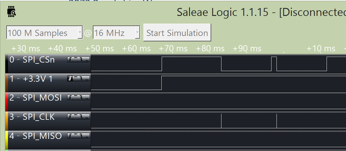
Figure 1. Failed SPI Boot.

Figure 2. Failed SPI Boot Attempt with Thumb Pressure on the ECP5.

Figure 3. Successful SPI Boot with Thumb Pressure on the ECP5.

Figure 4. X-Ray Image of the ECP5 IC as Originally Installed.

Figure 5. Close-up of Figure 4 with a PCB Pad Marked in Blue and a BGA Ball in Red.

Figure 6. X-Ray Image of the Newly Installed ECP5.

Thursday, April 30, 2015

Rev C bring up

I built the first rev C of Titan earlier this week, and I've been working to bring up the board. This has been the cleanest build yet. It did take about five hours to build by hand, but my process is getting better with each build.

So far I've confirmed that all of the power rails are operational, the on-board USB programming circuit works, and the FPGA can be programmed. The LED counter didn't run when I loaded titan_wiggle, so I'll need to debug a little tonight.

Figure 1. First Rev C.

Tuesday, April 14, 2015

Saturday, April 4, 2015

A different build


Today a helped a friend, Nick Huskinson, build a PCB board for his senior design project. The board implements a quad ADC using the Linear Tech LTC2170. Since Titan isn't ready yet, Nick designed this board for the Lattice ECP5 development card. Hopefully rev B will have an interface for Titan.

Figure 1. Nick's ADC Board (Ready for Relow).

Figure 2. Nick's ADC Board (After Reflow).

Wednesday, December 10, 2014

Second build of rev B


As Kevin mentioned yesterday, we were able to build a second rev B Titan using the ECP5 that we reclaimed from our rev A build. I'm still working to get the PCI Express interface to enumerate, but the build went well as the video above shows.

We've found a few clear errors in the PCB that we need to fix and we've already started some preliminary work on rev C. I'll outline what we found as soon as we have a more complete list.

Friday, November 28, 2014

And the sparks fly...

I'm still trying to wrap my head around it, but unfortunately I destroyed our only working Titan prototype while testing it. The build went very well, and I got a lot of good data from testing the card. While Kevin and I consider our next steps, I'll review how we got here.

Building

The rev B board assembly went very smoothly. I simplified the build by not loading the USB programming circuit, and I was able to place and reflow the board myself (including the two BGA parts). The only items that required manual rework after the build were two twisted capacitors and the switching power supply IC in a QFN package at U10. U10 also skewed in the same direction on the rev A build so we are going to examine this issue more deeply later.

Figure 1. U10, Skewed by a Pad.

We decided to simple remove U10 and bypass the 12V to 3.3V power supply and use the PCI Express connector's 3.3V rail instead. With U10 removed, this just required a simple mod-wire.

Testing

Prior to powering the board I measured the impedance to ground on each voltage rail:

RailLocation MeasuredImpedance
3.3VC866 kOhms
2.5V_AC604.8 kOhms
1.1V_AC314.3 kOhms
1.1VC5979 Ohms
2.5VC674.1 kOhms
1.5VC272 kOhms
     Table 1. Impedance Measurements.

RailLocation MeasuredVoltage
3.3VC863.472 V
2.5V_AC602.49 V
1.1V_AC311.099 V
1.1VC591.096 V
2.5VC672.480 V
1.5VC271.499 V
     Table 2. Voltage Measurements.

Using a Lattice USB programmer, I used Diamond to validate that the ECP5 was identified with a JTAG scan. I then loaded my titan-wiggle test project and two LED expansion boards to validate That 64 I/O pins (32 to each expansion header) all work as my video shows.

Next I rebooted the Linux PC that was powering Titan and used the lspci command see if the PCI Express interface enumerated; It did not enumerate. I was able to validate the PERSTn (the PCI Express reset signal) and REFCLK were being received by the FPGA. Titan-wiggle uses PERSTn as its reset; I simply issued a warm reboot (linux reboot command) and saw that the LED counter reset during the PC's reboot. I then changed the LED counter from the 50MHz oscillator to the 125MHz output from the PCIe core and the LED counting pattern speed increased as I expected.

This is when the damage to Titan occurred. The mod-wire bypassing U10 was connected to a 3.3V via very close to the PCIe connector. With Titan installed into the PC and powered I accidentally nudged the board and the mod-wire popped off the via. The wire was under tension and swung across the card, most likely contacting the 12V rail on nearby caps. This would have shorted the ECP5's 3.3V rail directly to 12V. I saw a spark and a little smoke. As we all know, it is nearly impossible to return all of the smoke to an IC once it escapes :p  I powered off the unit and checked the voltage rails and found that the 3.3V, 2.5V, and 1.1V rails were all shorted to ground.

While this is disheartening, mistakes do happen, and hopefully we can recover quickly. For now I will be focusing on firmware development using the Lattice PCIe Development Kit and developing theories about why the PCI Express interface did not enumerate

Tuesday, November 25, 2014

More signs of life

I used two Dione LED boards and the titan_wiggle FPGA project to validate that all of the expansion I/O pins work. Next step, PCIe!

Titan Lives!

All of the power rails on the rev B board come up correctly and the FPGA is detected in Diamond via JTAG!

More details tonight.

Rev B, assembled


Figure 1. Titan Rev B, Assembled.

I just finished assembling a rev B board. I decided to leave of the on-board USB programmer for now to simplify the build. I'll use an external USB programmer to program the ECP5 if the board checks out.

Monday, November 24, 2014

Rev B arrives

Figure 1. Titan, Now with Bigger Pads!

Figure 2. BGA Pad Size Comparison (Left: Rev A, Right: Rev B).

Rev B arrived today. If all goes well I'll assemble a board tonight!

Friday, November 14, 2014

Another picture of rev B

Two more pictures from PCB-Pool just arrived. These show the surface finish of the PCBs being built:

Figure 1. Titan rev B Top Side (Surface Finish).

Figure 2. Titan rev B Bottom Side (Surface Finish).

Friday, November 7, 2014

Making adjustments

Figure 1. Rev A of Titan, Assembled.

I posted a summary of our build experience with our first rev of Titan on the CES blog yesterday: Building Titan.

We completed the rev B updates to the artwork, released it on GitHub, and ordered new PCBs today. The changes are listed in the release notes on GitHub.

Saturday, October 11, 2014

Building Titan

Kevin and I spend the afternoon building Titan. We placed every part except the Lattice ECP5 FPGA. Since supply of the FPGA ICs are limited we are going to have a local contract manufacturer install it and X-Ray it to validate the solder quality.

We should be ready test later next week!

Figure 1. Placing Parts on Titan

Figure 2. Titan after Placing Most of the Small Passives.

Figure 3. Ready for Relow!

Monday, October 6, 2014

Tuesday, September 30, 2014

Titan is curing

I love PCB-Pool. They send pictures of your PCB during the assembly process (including the two latest pictures below). We will have the boards in our hot little hands early next week.

Figure 1. Top View of Titan

Figure 2. Bottom View of Titan


Tuesday, June 17, 2014

Panel Assembly

I just posted a new video where I assembled my first prototype panel from PCB-Pool. Check it out on the CES blog: http://customembeddedsolutions.blogspot.com/2014/06/in-todays-video-john-builds-small.html

Here's a picture of the logo (because I think it's cool):


Monday, June 9, 2014

PCB-Pool Panel

I received my first mini-panel from PCB-Pool today. At first glance it looks really good. The biggest surprise was that I got two stencils when I only expected one. There must be a mistake for the edge connector on the paste paste layer (they shouldn't be pasted), but that mistake means that I now know that you can get two stencils just by including the bottom paste layer!

Figure 1. Nice Box!

Figure 2. PCB Panel and Two Stencils!

Figure 3. Panel Close-Up

Friday, May 23, 2014

First panel ordered

I ordered my first mini panel from PCB-Pool this morning!

PCB Panel Combining Several Prototypes.

Monday, March 3, 2014

A swing and a miss

While checking the bityExpress-C board that I assembled, I found that most of the power rails were shorted to ground.  I inspected the PCB before assembly, but I did not check for power shorts.  After finding the shorts on the assembled board I checked my two remaining un-populated PCBs and found the same shorts.

I re-ran the DRC in Altium (my EDA tool) and it passes.  I opened a service ticket at OSH Park.  If this does turn out to be another error by OSH Park I may have to find another PCB house.

Saturday, March 1, 2014

Building bityExpress-C

Assembly and reflow of my first bityExpress-C board went well last night.  I'll test it later today and see how well it really went.  Below is a video of the process:


Finished bityExpress-C sn #1 assembly