This arrangement allows me to alternatively light either the red or green half of the bi-color LED. To light the green LED I tri-state the red I/O pins, then drive the green anode high and the green cathode low. Since adjacent pins are always either driven high or low I can identify BGA shorts.
While preparing to solder I ran quite a few temperature profiles. I used Altera's SMT Board Assembly Process Recommendations (AN-353-4.0) to design my profile. The target was to pre-heat at between 150 and 200 degrees Celsius for 60-120 seconds then heat between the eutectic and the CPLD's maximum temperature for another 60-120 seconds. I profiled to PCB using some thermocouples, a Meterman meter with an RS232 interface, and a simple python script that I wrote to plot the temperature data against my profile in real time:
The green line in the plot above is the temperature on the PCB where the CPLD will be installed. The yellow line is the temperature on the PCB at the component farthest away from the CPLD. With a verified profile, the next step was to align the stencil:
Apply the paste:
Carefully remove the stencil:
Place the components:
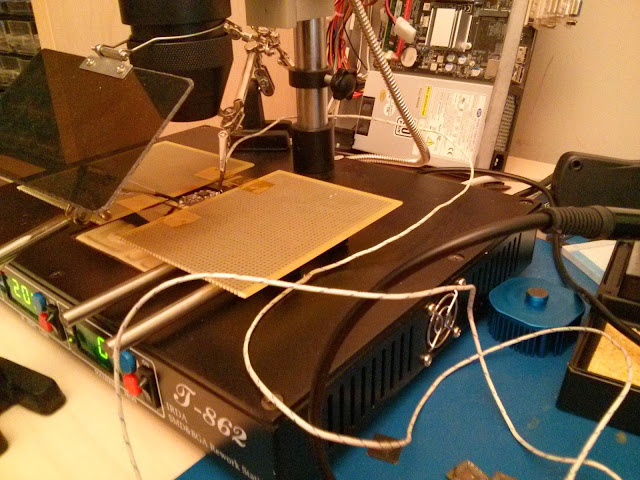
Place some thermocouples to monitor the heating:
Heat the board:
Test it:
Next I'll build a few more to see how repeatable my process is.


No comments:
Post a Comment